FAQ - Answers to frequently asked questions
Frequently asked questions in the category:
-
My roof pitch is less than 25° or more than 45°. What solutions does Skoberne offer here? +
In addition to the standard universal pitched roof tile, which covers pitches of 25-45°, Skoberne also offers a tile with a pitch of 5-25° and a version with a pitch of 35-55°. This covers a very wide range of roof pitches.
The aforementioned pitched roof tiles are available as a package variant or as individual items.
-
What solutions does Skoberne offer for penetrating a trapezoidal sheet metal roof or fibre cement roof (Eternit)? +
The following image documentation provides a non-verbal explanation of the solution from Skoberne. The DEKTITE product is explained in more detail on our website www.dektite.de.
The fixing screws with sealing washer included in the set are replaced with rivets for fibre cement installation. This must be pointed out when ordering.


-
How does the installation of the metal shaft cover (flexible) work? +
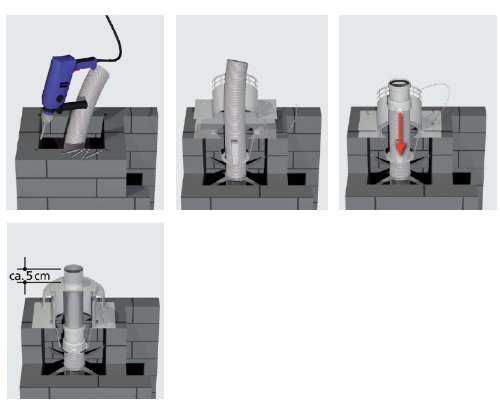
Once the flue gas pipe has been successfully installed, the outlet end is prepared for installation. To do this, 4 fixing points for the supplied M6 knock-in plugs are determined and drilled.
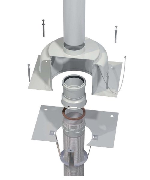
Then place the mouth transition to the metal manhole cover and the lower part of the manhole cover on top of each other and install on the manhole using the supplied knock-in dowels. The following pictures illustrate the components[JY1] .
Fit the retaining cable into the eyelet hole of the manhole base. Shorten the flexible pipe as required and connect it to the flex/rigid plastic adapter. Insert the metal end pipe and connect it to the plastic sleeve. Also thread the retaining cable into the eyelet hole of the weather bonnet. Slide the weather bonnet over the outlet pipe and snap it firmly onto the lower part.
-
What needs to be considered when connecting a new heat generator to an existing system? +
Pressurised exhaust gas ducts are system exhaust gas ducts. They must be designed to be standardised and compatible with the system. When connecting to an existing flue gas system, a number of aspects must be observed:
- Single-walled rigid or flexible: 20 mm
- Concentric: 0 mm
-
How does the transition from the single-walled flue gas pipe in the shaft to the concentric flue gas pipe in the heater take place? +
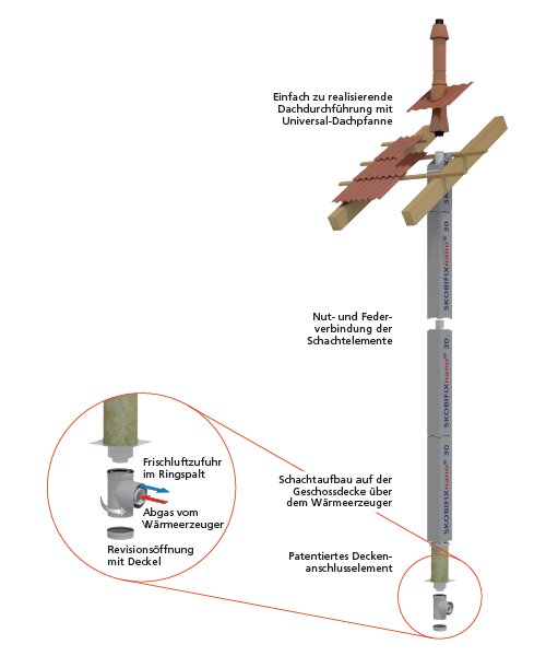
The ceiling connection element enables the transition between the shaft and the concentric flue gas pipe. The shaft rests and seals onto the ceiling plate duct and then the flue gas pipe and air concentric duct are male female push fit connected with that of the elbow (connecting T-piece).

elow is an illustration using the SKOBIFIX shaft system as an example for better understanding. The PORIFIX and UNIFIX products have a comparable ceiling connection element. This connection solution is also patented.
-
Are external components or pipe runs possible in combination with the flue gas pipe? +
Non Skoberne components(third party products) are not permitted in the flue gas system. The functional, fire and stability safety of flue gas systems must not be impaired by use of non Skoberne group manufactured external components and equipment. This is described in point 6.6 of the DIN V 18160 standard. Particularly critical are third party (other suppliers lines) in connection with single-walled flue gas pipes that can hinder longitudinal movement.
-
How many spacers should be installed in the shaft? +
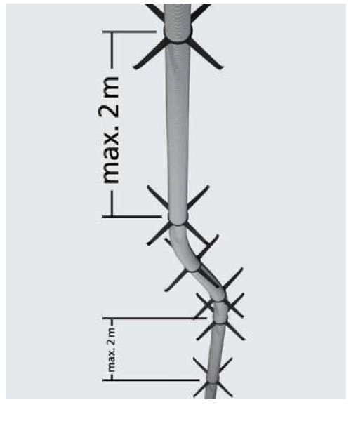
Spacers must be installed every 2-3 metres for rigid systems. A spacer must be placed before and after each moulded socket in the area of the joints.
When installing the flexible flue gas pipe, a spacer must be provided at least every 2 metres. In addition, a spacer must be provided before and after each moulded joint piece and at each change of direction.
It is important to remember that the curved ends of the spacers must always point in the direction of the flue gas to ensure the longitudinal movement of the flue gas pipe. It should also be noted that too many spacers can also hinder the longitudinal movement of a rigid flue gas pipe.
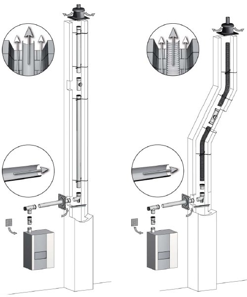
Illustration of the rigid flue gas pipe:
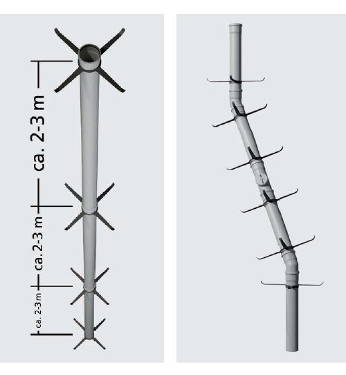
Illustration of the flexible flue gas pipe:
-
What does "ambient air-dependent" operation mean? +
The firing system and flue gas system must be considered from various points of view:
Gas appliances are differentiated according to the flue gas discharge and the combustion air supply, among other things. Type B appliances are operated depending on the room air.
The combustion air is therefore taken by the fireplace from the installation room or the installation level. The following are a few examples to illustrate this:
-
What is the purpose of the air intake piece with regard to external wall installation? +
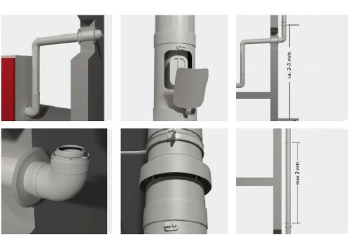
The function of the air intake piece is to ensure the supply of combustion air to the heat generator. The air intake piece acts as a bypass and can be positioned anywhere in the external wall system. The air intake above ground level is particularly important for wall penetrations below ground level.
We recommend installing the air intake piece at a height of up to 3 m above ground level.
-
What is multiple occupancy (MFB)? +
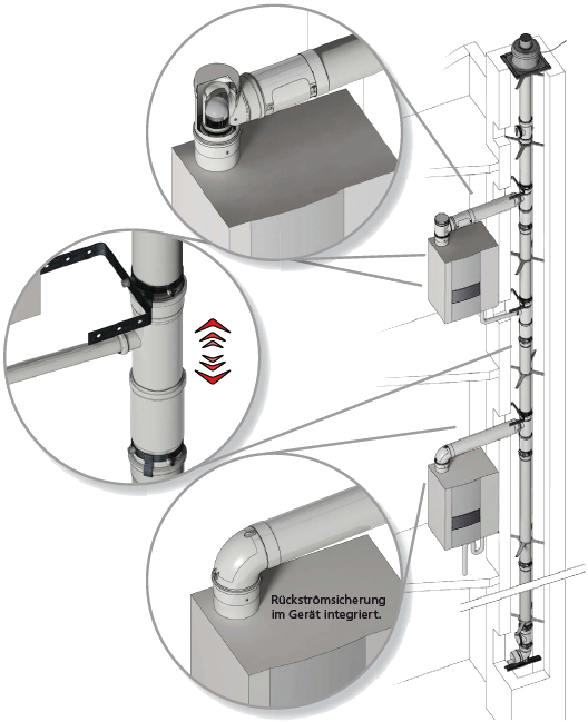
A multiple connection (MFB) describes the type of connection that collects several appliances on just one vertical flue gas pipe.
Multiple firing systems (MFB) are nationally (D) certified by the German Institute for Building Technology (DIBt). The DIBt refers to the Model Firing Ordinance (M-FeuVo 2005) paragraph 7 section 4.
The Skoberne approval is Z-7.5-3256.
-
Does the Skoberne shaft have to pass through the floor slabs? +
The SKOBERNE shaft elements must be installed through all storeys. They usually start above the storey ceiling of the heat generator and end in the area of the roof cladding. For pitched roofs, this means approx. 2-3 cm above the roof battens. In the case of a flat roof variant, the shaft is routed to below the last roof seal.
-
How is a flue gas pipe with external wall installation constructed? +
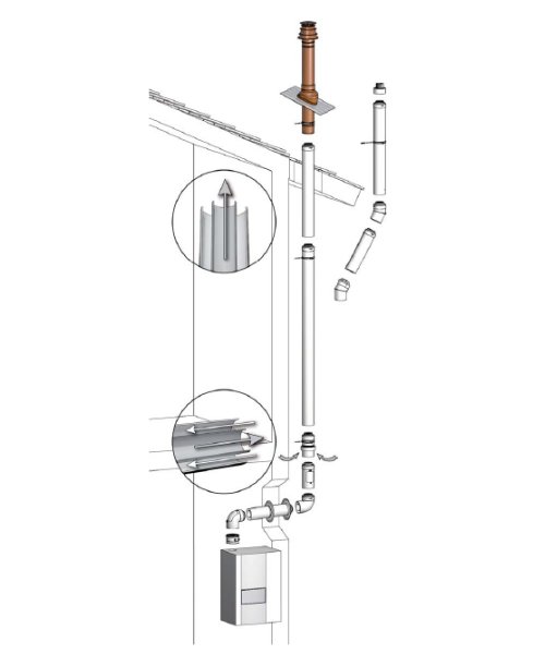
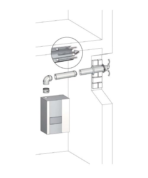
In principle, the functional components deflector elbow, inspection piece and a so-called air intake piece must be installed outdoors. The sequence is flexible and can be adapted depending on the situation and the requirements of the chimney sweep/chimney sweep.
The air intake piece must be positioned in such a way that a permanent air supply is ensured. Protection against external influences must be guaranteed. We recommend positioning the air intake piece up to 3 metres above ground level.
Below is a design example and a simple wall duct (in Germany only up to 11 kW) as an external wall solution:
-
How does the installation of the metal shaft cover (rigid) work? +
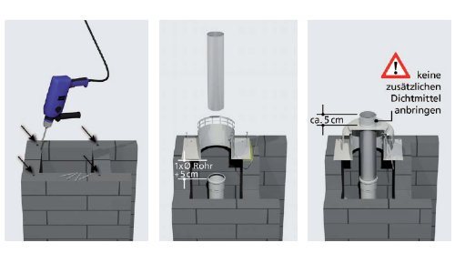
Once the flue gas pipe has been installed, the outlet end is prepared for installation. To do this, define and drill the 4 fixing points for the M6 knock-in plugs supplied. Then fit the lower section using the supplied knock-in plugs. It is essential to use a suitable weather and UV-resistant sealant (not supplied) between the chimney head and the base of the shaft cover. Insert the (metal) flue pipe through the shaft cover and insert it into the last pipe socket. It is important that the metal end pipe protrudes into the shaft by at least the length of the pipe diameter. Fit the retaining cable into the eyelet hole of the lower part of the shaft and the weather bonnet. Slide the weather bonnet over the outlet pipe and snap it firmly onto the lower section. The outlet pipe must end about 5 cm above the weather bonnet.
-
What aspects need to be considered for double flue gas systems? +
In the case of a multiple flue chimney stacks, with potentially widely differing temperature flue gases being exhausted at the stack top, often a combination of a ‘hot’ chimney (eg solid fuel firing) outlet next to low temp exhaust (eg a flue gas pipe with air intake connected to a gas condensing boiler), the flue gas outlets must be given special consideration.
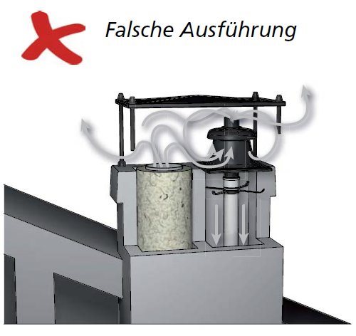
There are two important aspects to consider here. On the one hand, the possible fire hazard of the plastic flue gas pipe through from the adjacent hot chimney and, on the other hand, the risk (in a C9 installation, a counterflow operation) of the flue gases being sucked into the combustion air supply intake at the condensing boilers terminal.
Detailed information on this is provided in DIN V 18160.
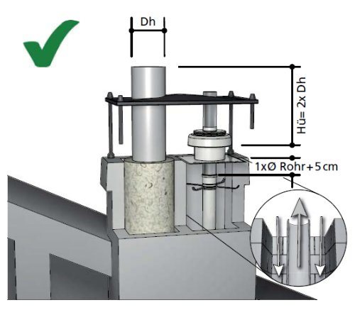
Skoberne offers two versions of Terminal manhole covers for this purpose. One is a plastic shaft cover and terminal cap, the second being a metal manhole shaft cover, cap and with a metal outlet pipe. Under certain conditions, such a multiple flueway chimney stack -pass flue gas system can also be satisfactorily achieved realised with a plastic shaft manhole cover by ensuring adequate separation distances.
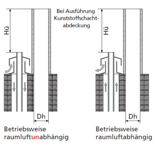
When a standard solid fuel fired burner (flue gas temps up to 400 °C) is adjacent to a condensing boiler flue outlet, then the distance dimension Hü must be at least 1000 mm, and must be so arranged with the hot flue outlet above the condensing flue outlet. The separating wall (tongue) between shaft and chimney) must be at least 100 mm thick and the annular gap between the shaft and the flue pipe must not be less than 15 mm.
The requirements for metal shaft covers and terminal caps manhole in multiple use chimney stacks with a risk of soot fire are met by the components offered by Skoberne. The distance dimension Hü can be significantly reduced if using with metal terminal covers, caps and outlet pipes.
The following drawings explain the previous explanations.
-
How is the combustion air supplied? +
The "condensing chimneys" SKOBIFIX, PORIFIX and UNIFIX are complete concentric systems consisting of a fire protection shaft and plastic flue gas pipe. As a rule, the appliance (usually condensing boiler or CHP unit) are operated independently of the room air( ie room sealed )meaning the combustion air is drawn in from the roof terminal, using the counterflow principle and fed to the burner via the supply air ring gap. The following illustration with details explains the principle using the arrow directions.
Blue= Supply air
Red= Exhaust gas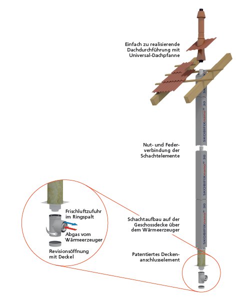
-
When should the flue gas pipe be operated with a safety temperature limiter (STL)? +
Skoberne plastic flue gas ducts are tested up to a flue gas temperature of 120 °C. The appliance manufacturers confirm the maximum possible flue gas temperature when entering the flue gas duct via their type approval. In case of doubt, Skoberne offers fittings for the installation of a flue gas safety temperature limiter.
-
How are inspection openings correctly planned and installed? +
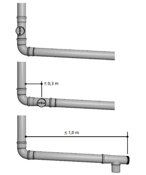
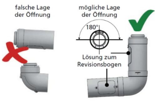
Regulations on the installation of inspection openings can be found in DIN V 18160-1(-5). The lower inspection opening installed in accordance with the standard makes it possible to dispense with an upper inspection opening in the vertical section (up to 15 metres in length), thus eliminating the need to inspect the opening from the chimney outlet and so also eliminating the need for complex and cost-intensive safety equipment on the roof surface.
The procedure and possible instructions must be agreed with the responsible district chimney sweep.
-
What is a CE mark and what information does it contain? +
With the CE marking, the manufacturer declares in accordance with the EU regulation "that the product complies with the applicable requirements set out in the Community harmonisation legislation on its affixing". The abbreviation CE stands for Conformité Européenne, which loosely translates as Euro-compliant. In addition to the logo, the CE mark also consists of a series of numbers and digits.
The new Construction Products Regulation of the European Union, to which the draft standard 14471:2013 refers, came into force on 1 July 2013. This has already resulted in the following changes:
In future, construction products that are covered by harmonised European standards must also have so-called declarations of performance (DoP) in addition to the CE marking (proof of permissibility of "placing on the market"). This declaration of performance replaces the manufacturer's previous declaration of conformity and must be made available to the customer.
We provide you with the line declaration in the following table and the following link:
DoP - Declaration of Performance No. 9184-V06 DoP dated 03/03/2022
-
What annular gap must be available around an exhaust pipe? +
The annular gap around the flue gas pipe is a mandatory requirement for various reasons. First and foremost is the aspect of operational safety:
To prevent fold back of flex pipe and so to prevent condensate pooling in serpentine bends which could effectively create airlocks
To maintain correct combustion air intake
Longitudinal movement of the exhaust pipe
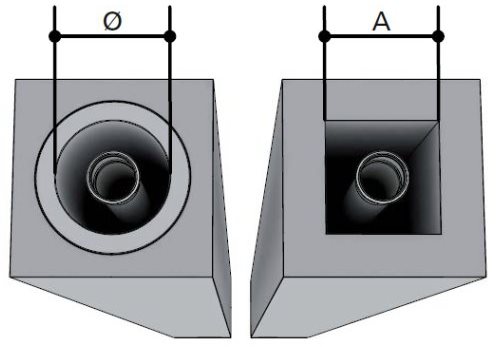
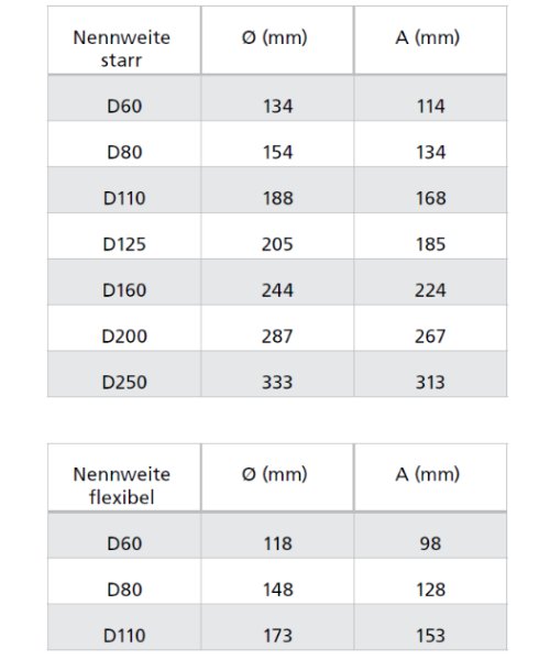
In addition, the installation and removal aspects must be considered. It must be possible to install and remove the flue gas pipe safely and without damaging it. The following cross-sections take into account the required minimum annular gap for room air-dependent operation (room sealed principle). This is 3 cm for round shaft cross-sections and 2 cm for square or rectangular shaft cross-sections, measured between the inner wall of the shaft and the outer wall of the flue gas pipe. The minimum annular gap is also generally required as described above for room air-independent operation (counterflow principle). However, it is possible to reduce the annular gap by means of mathematical verification, provided that the installation or removal is sustainable. This point is dependent on many factors and must be taken into account at the planning stage.
-
What is a non-return valve and what purpose does it serve? +
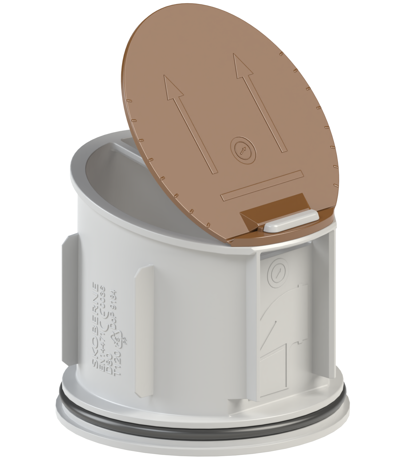
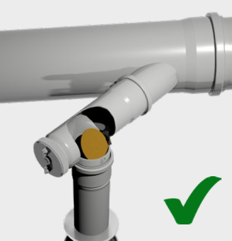
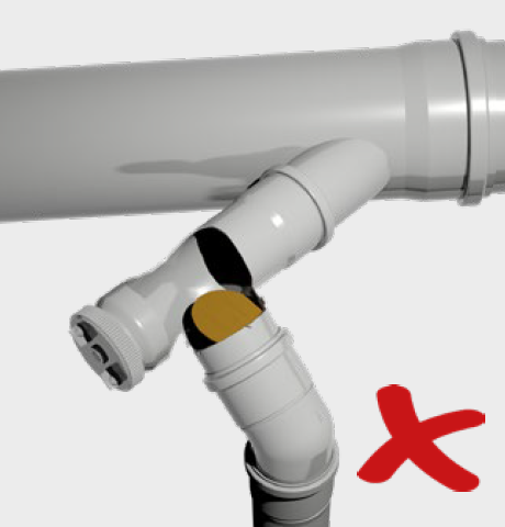
Backflow prevention devices are required for pressurised exhaust gas systems with several appliances (KAS, MFB). It must be ensured at all times that exhaust gases cannot escape in dangerous quantities. A pressurised design requires a device that prevents flue gases from escaping or flowing back through an appliance that is out of operation, for example. Non-return valves are tested in accordance with DVGW Code of Practice G635, but their use must be agreed with the respective boiler manufacturer.
The solutions for non-return valves differ in terms of the possible installation position, the type of flue gas or supply air routing and the mode of operation by gravity or external energy.
Below are some examples of Skoberne solutions and their correct application:
-
Shaft systems +
With the introduction of plastic flue gas pipes, the topic of fire protection has arisen simultaneously since 1987 (when the company was founded). This is because every flue gas pipe must be routed in a shaft within the building. Shafts for flue gas pipes are important in many ways.
- Shafts serve as cladding
- Shafts serve as impact protection
- Shafts serve as fire protection
- Shafts are used for rear ventilation of the system
- Shafts act as a gas-tight protective cover around the flue gas pipe
- Shafts are generally used for the safety of the flue gas system
- Shafts are used for easy assembly and disassembly
For the afore mentioned reasons, it was important for our company to find solutions from the outset that fulfil the tasks and thus meet the requirements of our customers.
The result is our SKOBIFIX, UNIFIX and PORIFIX shaft systems, which are specially tailored to the following target groups.
- SKOBIFIX for heating engineers and HVAC installers
- UNIFIX for building tradesmen such as chimney builders
- PORIFIX for self-builders
-
Are there specific fire protection requirements for multiple occupancy (MFB)? +
Fire protection is an important point in the case of multiple occupancy, i.e. the connection of several flue gas pipes to the vertical section. The vertical flue gas pipe is routed in a shaft/chimney with a fire resistance period of 90 minutes.
Preventing the spread of fire from storey to storey is crucial and must be ensured. Corresponding independent tests have led to the granting of the general technical approval (Z-7.5-3256).
See also the question "What aspects need to be considered with the multiple occupancy system (MFB)?".
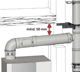
For fire protection reasons, the concentric flue gas pipe must maintain a distance of 50 mm from combustible components in the case of multiple occupancy. See the following illustration:
-
How does the connection technology of the flexible gas flue system work? +
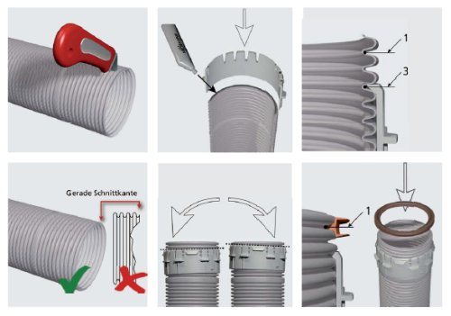
The flexible pipe is cut straight. Always apply Skoberne lubricant to the outside of the flexible pipe in the connection area. Position the mounting ring in groove no. 3 with a slight tilting movement downwards. Then pull the seal (two lips on the outside) into groove no. 1 and also coat with lubricant.
The flexible pipe can now be connected with the corresponding adapter (on all moulded parts). It is essential to ensure that the 4 lugs engage correctly. The required exhaust direction of the adapters can be recognised by an embossed arrow.
The connections can be released at any time with a twisting motion.
The following illustrations are provided for clarification:
-
What aspects need to be considered with the multiple occupancy system (MFB)? +
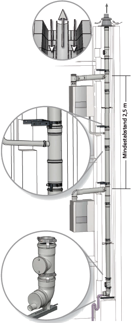
The use of Skoberne components as a multiple installation in the shaft is covered by the general technical approval of the DIBt (Deutsches Institut für Bautechnik) Z-7.5-3256. Due to the considerable longitudinal expansion of plastic flue gas pipes, the pipes and fittings in the vertical shaft are connected to each other in a force-fit manner in order to absorb and control the expansion. For each horizontal section (connecting pipe), a sliding sleeve is connected upstream of the connecting T-piece in the vertical section to compensate for the linear expansion.
The condensate is collected and discharged centrally at the bottom of the multiple occupancy unit. Operation in overpressure requires a siphon with a sealing water height of at least 150 mm.
The condensate from the horizontal connection pipe is discharged via the appliance or optionally into the vertical part of the flue gas system.
Below are the requirements from the regulations in brief:
Minimum annular gap/cross-sectional area
Exhaust pipe dimension Minimum specifications for square shaft cross-section
Minimum specifications for round shaft cross-section
D 110 175 195 D 125 200 220 D 160 250 280 - Room air-independent operation of the gas appliance
- Air exhaust system with metal supply air jacket
- At least 50 mm distance between the air exhaust pipe and flammable components
- Max. 10 gas appliances up to max. 30kW each
- 2.5 m minimum distance between the flue gas inlets
-
When do I use a flexible flue gas pipe? +
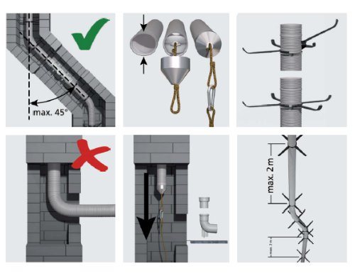
A flexible flue gas pipe is used when, for example, it would be impossible or unnecessary to use a rigid pipe, usually in the case of changes in direction in the chimney/flue.
The variations in direction from vertica must not exceed an angle of 45°, as there is a risk of damage to the flexible flue pipe and a risk of failure of condensate to adequately drain down. When using a flexible flue gas pipe, special care must also be taken during installation. The flexible pipe must not be pulled over sharp edges and must not rest against the shaft cheek (friction due to thermal expansion and contraction).
The following illustrations are provided for clarification:
-
How large must the ceiling openings around the shaft be? +
We answer these questions, among others, in the order forms on the first page, which should already answer the typical questions. We provide the following links to help you answer these questions about the right product:
- SKOBIFIXnano 30
- SKOBIFIXXs 30
- PORIFIX 90
- UNIFIX 165 mit Abgasleitung D80
- UNIFIX 165 mit Abgasleitung D110
- UNIFIX 210 mit Abgasleitung D110
-
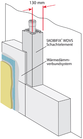
Does Skoberne offer a shaft brick solution that can be integrated into the thermal insulation? +
The SKOBIFIX ETICS product solutions have been specially developed for this application. A patent has also been granted for the solution.
Further information on the product can be found in the download area of the shaft systems.
-
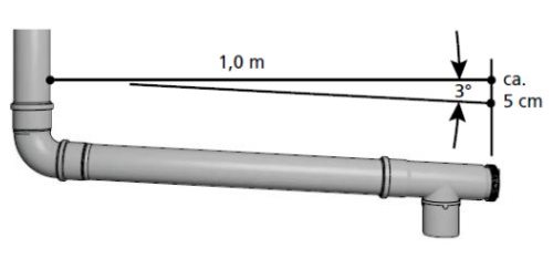
What aspects need to be considered when discharging the condensate? +
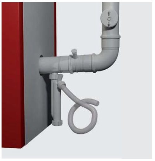
The acidic condensate must be able to drain off unhindered and without any problems at all times. It must not remain in the sockets, which would result in a concentration of acid and possible damage. Accordingly, the connecting pipe must be laid with a gradient of 3° (approx. 5 cm/metre).
Possible regulations for discharging condensates into the wastewater network must be obtained regionally. In case of doubt, the German Association for Water, Wastewater and Waste (DWA) offers corresponding guidelines.
-
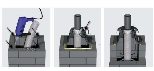
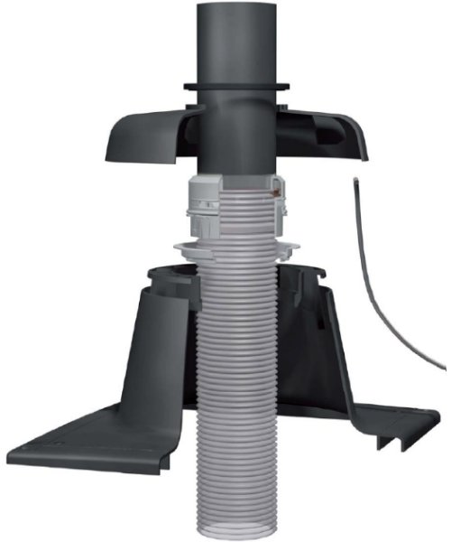
How does the installation of the plastic shaft cover (flexible) work? +
Once the flue gas pipe has been installed, the outlet is prepared for installation. Drill holes at the 4 fixing points for the M6 knock-in plugs supplied. Then mount the lower section using the supplied knock-in plugs. Use a suitable sealant (weather and UV-resistant) between the chimney head and the base of the shaft cover. Insert the reducing ring (nominal width 60 and 80 only) into the lower part of the shaft cover and thread the flexible pipe through it. Slightly lever up the flexible pipe and connect it to the black orifice pipe. Fit the retaining cable into the eyelet hole of the manhole base. Also fit the retaining cable in the eyelet hole of the weather bonnet. Slide the weather bonnet over the outlet pipe and snap it firmly onto the lower section.
-
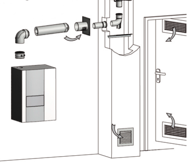
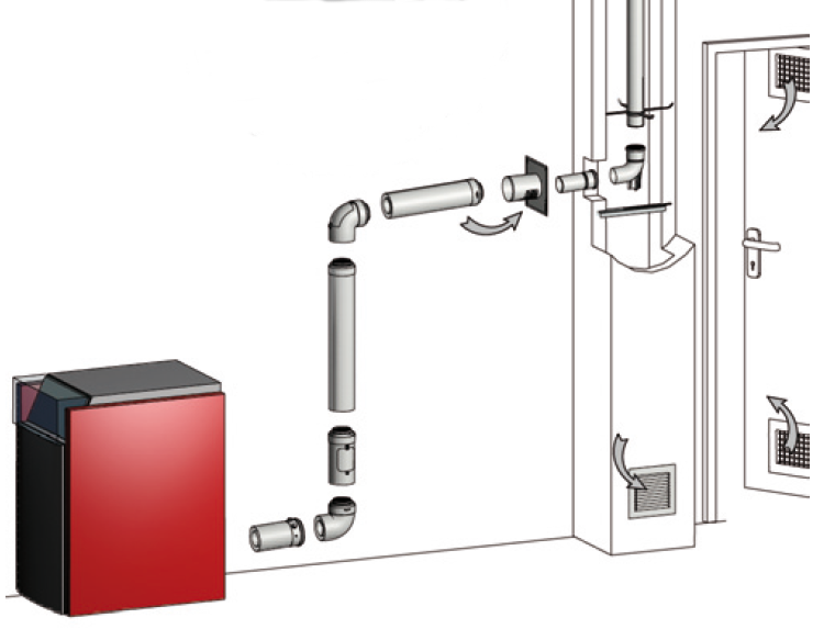
What is meant by ‘room air dependent’ operation with a concentric flue gas pipe? +
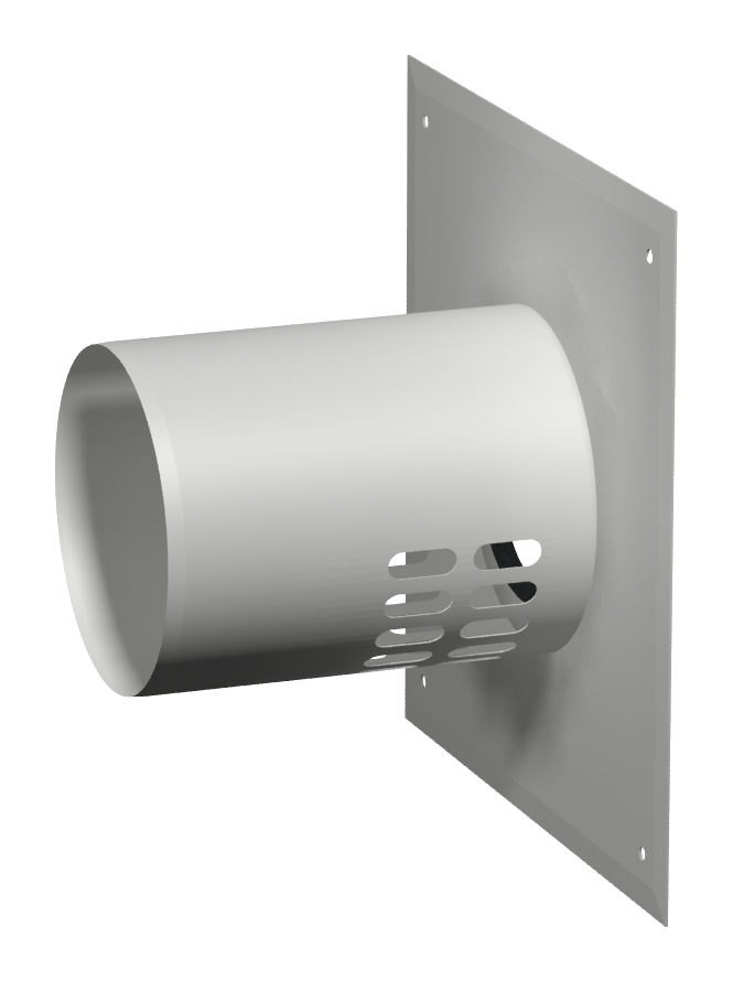
It is possible to use a so-called room air intake concentric ventilation wall plate (classification B3), which is installed in the horizontal connecting pipe. This has air inlets to supply the appliance with combustion air. The B3 wall plate, is attached to the shaft wall onto which the concentric connecting pipe is also installed. The advantages at a glance:
- No ventilation opening from the outside is absolutely necessary
- Avoids contaminant particles/soot/debris from shaft void being drawn in with the combustion air
- Installation is simplified by using the air vented B3 concentric wall plate.
- Controlled linear expansion
- Visual advantages
Here are some examples:
-
Which inspection openings do I need to provide for the shaft systems? +
DIN V18160 explains the requirement for inspection openings by application in great detail. For use as a "condensing chimney", it can be assumed that no cleaning above the roof or cleaning in the attic area is required up to a vertical pipe length of 15 m if an inspection opening complying with the regulations has been installed in the horizontal connecting pipe. This generally applies to the SKOBIFIX and PORIFIX products. The UNIFIX product range can sometimes exceed this length, so that an additional inspection opening is required up to 5 m below the outlet, unless the outlet can be seen above the roof.
Please also refer to the drawings in the technical information for the relevant products, which can be found in the download area of the website.
Regardless of the requirement for an exhaust-side inspection, the supply air ring gap must be provided with the option of inspection. Skoberne products usually work with the ceiling connection element, which allows for a supply air inspection. Shafts without a ceiling connection element are planned with a supply air inspection in the floor area.
-
Which tool is used to insert a flexible flue gas pipe into the shaft? +
The flexible pipe is usually pulled down into the shaft via the top opening. We recommend using the Skoberne pulling-in aid. Squeeze the flexible pipe to an oval shape to allow insertion and anchoring of the metal disc in the groove of the flexible pipe. Then pull the cone over the flexible pipe to secure the connection. A rope is attached to the loop, which is then used to pull the flex tube downwards.
The following illustrations are provided for clarification:

-
What is the thermal elongation of plastic exhaust pipes? +
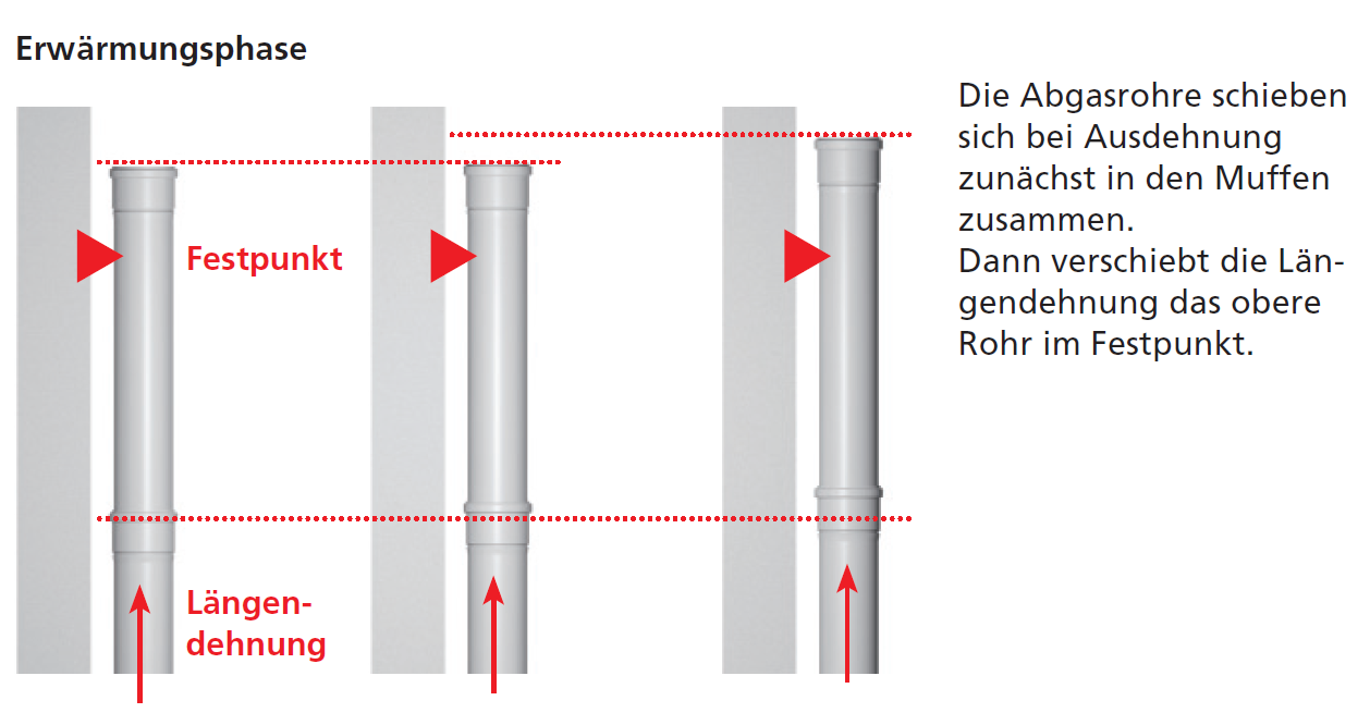
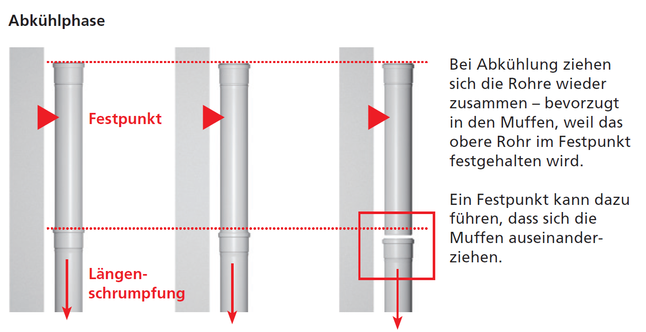
Plastic exhaust pipes have an elongation that should not be underestimated. It is therefore important to ensure free longitudinal movement so that the exhaust pipe is not pulled apart when it heats up or cools down. The following diagrams explain the subject. A detailed document describing the effects in various situations can be found at the following internet link: SKOBINEWS
The underestimated linear expansion

-
What maximum temperatures and pressures are permitted? +
Skoberne flue gas pipes are tested and approved up to a flue gas temperature of 120 °C and a pressure of 5000 Pa (Pascal). All nominal widths and components are classified as H1 (high pressure).
-
When is a concentric flue gas pipe in the shaft recommended? +
In addition to the usual application on the outer wall or the connecting pipe, concentric pipes (LAS pipes) are also used in dilapidated and brittle shafts/chimneys. Especially where adhering soot particles cannot be extensively removed. A concentric flue gas pipe in the shaft/chimney eliminates the risk of soot particles being sucked in. Corrosion in the condensing boiler caused by poor combustion air is therefore ruled out.
Furthermore, it is advantageous to see that the entire firing system together with the flue gas and supply air sides form a single structural unit.
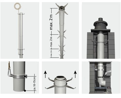
Special attention must be paid to the installation and removal of this type of flue gas and supply air duct. Illustrations are provided below.
-
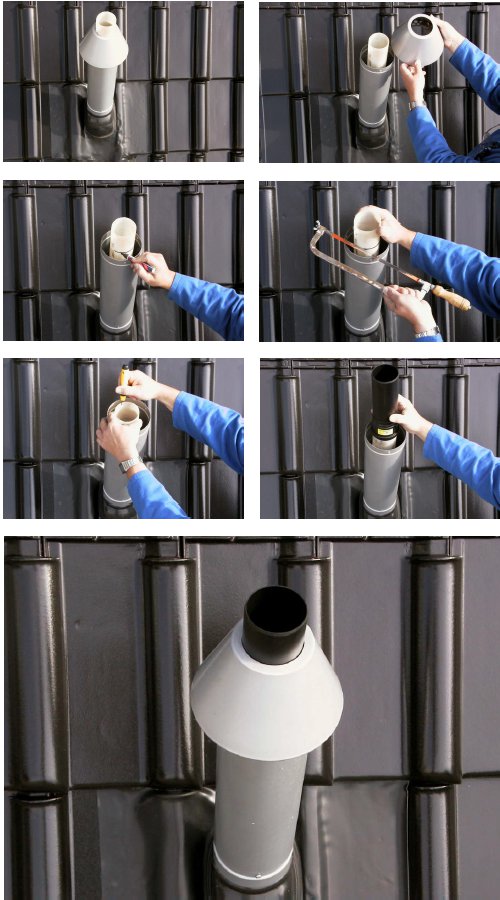
My exhaust pipe has become brittle due to UV radiation. What solutions does Skoberne provide? +
From 2001 to around 2003, white or translucent flue gas pipes were also used in the outlet area. At that time, this was the state of the art and there was no experience that the UV radiation would damage the pipe relatively quickly in conjunction with the acidic condensates. The embrittled pipe can simply be cut off in the orifice area. A UV-stabilised end pipe with a sleeve and integrated condensate return provides the finishing touch.
The following assembly steps explain the solution.
-
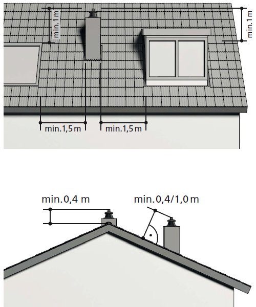
What heights or distances of the flue outlet above the roof and to windows must be observed? +
The specifications of the firing regulations of the relevant federal states (LFeuVo) and the TRGI/TRÖL (Technical Rules for Gas and Oil Installations) must be observed in particular. As a rule, a distance of 40 cm from the roof surface is sufficient for room-sealed fireplaces with a blower up to 50 kW output.
In the case of room air-dependent operation, a distance of 1 m from the roof surface must be maintained or the routing over the ridge must be at least 40 cm. Distances to openings in rooms and roof structures must be maintained in accordance with the above regulations. As a rule, windows and ventilation openings within a radius of up to 1.5 m must protrude by 1.0 m.
In the federal state of Bavaria, windows and ventilation openings must protrude by 1 metre within a radius of up to 8 metres.
-
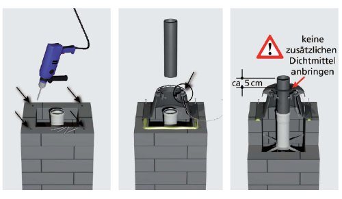
How does the installation of the plastic shaft cover (rigid) work? +
Once the flue gas pipe has been installed, the outlet end is prepared for installation. To do this, define and drill the 4 fixing points for the M6 knock-in plugs supplied. Then fit the lower section using the supplied knock-in plugs. It is essential to use a suitable sealant (weather and UV-resistant) between the chimney head and the base of the shaft cover. Push the chimney pipe (nominal width 60 and 80 UV-stabilised) through the shaft cover and insert it into the last pipe socket. Insert the retaining cable into the eyelet hole of the manhole base and the weather bonnet. Slide the weather bonnet over the outlet pipe and snap it firmly onto the lower section. The outlet pipe must end about 5 cm above the weather bonnet.
-
What needs to be considered when connecting a new heat generator to an existing system? +
Overpressure exhaust pipes are system exhaust pipes. They are standardised and system-compatible. When connecting to an existing exhaust system, a few aspects must be observed:
- Exhaust system in perfect condition?
- Is the flue gas system classified for the connection of the current condensing boiler?
- Is the flue gas system tight or has it been inspected by the responsible district chimney sweep?
- Is the exhaust system correctly dimensioned in terms of cross-section and length?
A comprehensive check before connection is strongly recommended.
If in doubt, and recommended anyway, replace the "old" seals with new ones. It may be necessary to replace the entire flue gas system. -
What distance must be maintained between the Skoberne shaft systems and combustible building materials? +
All complete systems or "condensing chimneys" from Skoberne, i.e. the combination of plastic flue gas pipe (up to 120 degrees Celsius) and fire protection shaft, can be planned and installed without a specific distance to combustible components. This therefore applies to the complete systems SKOBIFIX, PORIFIX and UNIFIX if they are used in their entirety.
-
Does an exhaust gas pipe have to be installed so that it can be dismantled? +
When planning and installing a flue gas pipe, it is essential to ensure that the installation is sustainable. The life cycle of a combustion system is limited. New condensing boilers often place new demands on the flue gas system, so it must be possible to dismantle them easily and without great effort.
This basic requirement is also contained in the guideline for the approval of flue gas systems (Deutsches Institut für Bautechnik). A comprehensive warranty is only possible under these conditions.
Further information and effects on the subject of "easy dismantling" can be found at www.skobinews.de.
-
How large must the gradient of an exhaust gas pipe be? +
One of the most important requirements during planning and execution is that the necessary 3° gradient in the direction of the appliance is observed during installation. The gradient is specified by 87° alone. In other words, the slope of 3° corresponds to a height difference of 5 cm over a length of 1 metre. The reason for this requirement is to ensure that the acidic condensate drains off properly, back to the boiler or drain point. The concentration of acid, which can result in damage to the seal, must be and is therefore avoided.
-
Is every flue gas pipe to be dimensioned or designed? +
The boiler and flue installation configuration dimensioning is carried out according to the calculation method of EN 13384-1 and 13384-2. Not every flue gas system has to be calculated. Boiler manufacturers often have diagrams and data available that have been created on the basis of the aforementioned standards and therefore provide a sufficient basis for planning.
-
What points need to be considered before installation? +
The regional building regulations must be observed before installation. The master chimney sweep will be happy to provide information.
You can find the most authorised chimney sweeps here, for example.
The following points should be checked and assessed before installation:
- Complete documentation for flue gas design (calculation according to EN 13384, or data from the boiler manufacturer)
- Quality of the chimney (shaft)
- Sufficient and clean air supply
- Positioning and number of inspection openings
- Safety equipment (for work that has to be carried out on the roof or façade)
- Keep flue gas paths as short as possible. Exhaust gases should primarily be routed via the roof.
- The socket of the flue gas pipe always points in the direction of flow of the flue gases.
- Complete scope of delivery
- Only use original parts.
- Check the fit of the seal in all pipe and moulded parts before connecting.
-
What is a cascade (KAS)? +
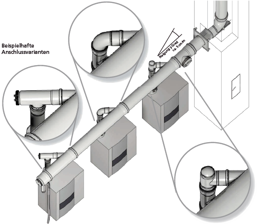
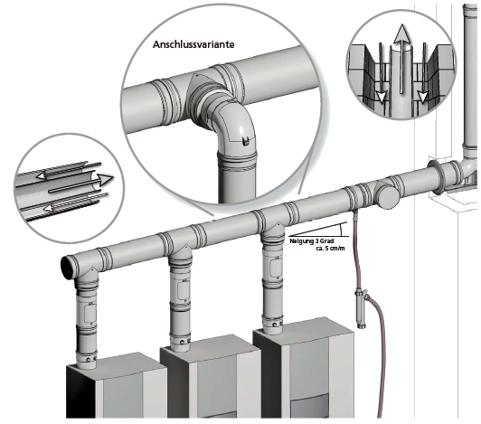
Cascade (KAS) describes the connection variant that collects several appliances on a connecting pipe (horizontal) and connects them to the vertical part of the flue gas system with only one connection.
Cascade systems (KAS) with their simple connection to the vertical flue gas system fall under the regulations of the so-called single occupancy. This corresponds to the EU standard EN 14471 for plastic flue gas pipes and is a prerequisite for CE labelling.
Here are some examples of applications:
-
When is a concentric flue gas pipe in the shaft recommended? +
In addition to the usual applications, concentric pipes (exhaust/air system pipes) can also be used in shafts and chimneys where the brickwork facings have become dilapidated and/or brittle.
Use of a concentric flue gas pipe in the shaft/chimney will also eliminates the risk of soot particles being sucked into the boiler air intake, from surfaces Especially where adhering soot particles cannot be extensively removed. Corrosion in the condensing boiler caused by contaminated poor combustion air is therefore ruled out.
Furthermore, it is advantageous to know see that the entire firing system together with the flue gas and supply air combined system sides forms a single structural unit.
Special attention must be paid to the installation and removal of this type of flue gas and supply air duct.
Illustrations are provided below.

-
What is the difference between the products SKOBIFIX®, PORIFIX® and UNIFIX? +
SKOBIFIX®, PORIFIX® and UNIFIX are product names for different systems. All are solutions for "condensing chimneys", i.e. being of the combination of a plastic flue gas pipe within and a fire protection brick. The systems differ primarily in their dimensions and wall thickness, which largely determines their fire resistance.
All three solutions are designed so that they start above the storey ceiling of the boiler and end with the roof surface. The exhaust gases are discharged above the roof via a special roof duct in the form of a "stub chimney".
The SKOBIFIX® systems are F30 solutions for use in detached and semi-detached houses. A distinction is made here between the XXS variant with exhaust pipe D80 and SKOBIFIX®nano with exhaust pipe D60.
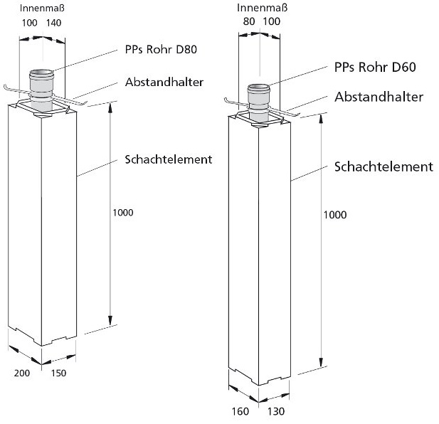
UNIFIX and PORIFIX® are systems with a 90-minute fire resistance period. These also differ primarily in the shaft dimensions and dimensions of the flue gas pipe, as follows……
PORIFIX® - Shaft with external dimensions 210x210 mm and flue gas pipe 60-80 mm
UNIFIX165 - Shaft with external dimensions 240x240 mm and flue gas pipe 80-110 mm
UNIFIX210 - Shaft with external dimensions 300x300 mm and flue gas pipe 110-125 mm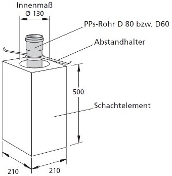
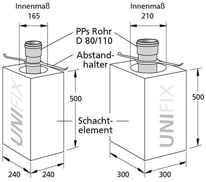
Larger brick sizes are also available for larger flue gas pipes.
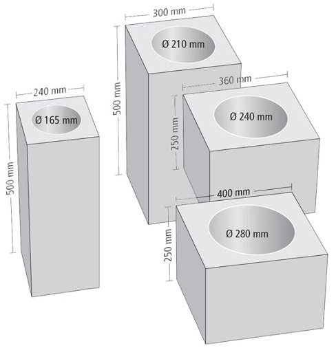
-
How many retaining clips do I need for a SKOBIFIX, PORIFIX or UNIFIX structure? +
SKOBERNE retaining clips can be used every 2-3 metres (however, at least one retaining clip should be used per storey). This applies to all shaft systems, whether SKOBIFIX, PORIFIX or UNIFIX, for standard storey heights of up to 3m.
-
My flue pipe is brittle in the terminal’s outlet area. What is Skoberne's refurbishment solution? +
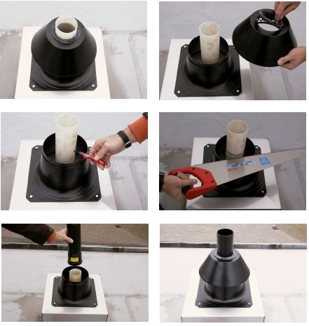
From 2001 to around 2003, white or translucent flue gas pipes were also used in the outlet area. At that time, this was the state of the art and there was no experience that the UV radiation would damage the pipe relatively quickly in conjunction with the acidic condensate. The embrittled pipe can simply be cut off in the terminal’s outlet mouth area. The new termination is then recreated with a UV-stabilised end pipe, with a sleeve and integrated condensate return.
The following assembly steps explain the solution.
-
How much adhesive do I need for a "typical" SKOBIFIX, PORIFIX or UNIFIX structure? +
The SKOBERNE special adhesive 3 kg for SKOBIFIX shaft elements is sufficient for approx. 10 - 12 connections. This means that one container of adhesive per property (eg a single house) is sufficient.
For the PORIFIX/UNIFIX shaft elements, the special 12 kg adhesive is sufficient for approx. 10 - 15 connections. This means a shaft length of up to approx. 18 metres.
-
What does the coaxial roof duct above the roof look like and what colour variants does Skoberne offer? +
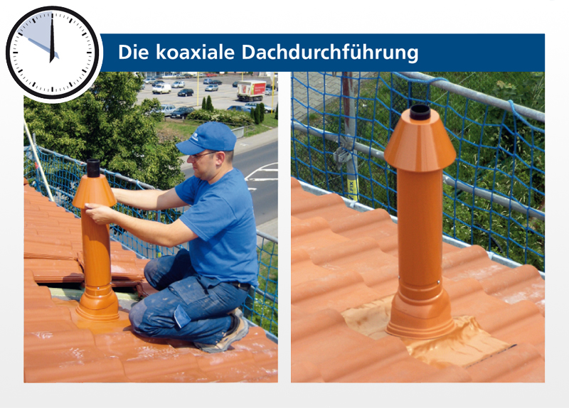
The following image shows a roof penetration of the SKOBIFIXnano 30 system in the colour "roof tile red". According to the RAL colour scale, the colour is listed as RAL8023. The roof ducts are available in three colours as standard:
RAL 8023 - roof tile red
RAL 9005 - black
RAL 9006 - silver lacquerPrimed roof ducts are also available, which can be produced in a suitable colour according to customer requirements.
Stainless steel versions are also available for certain products.
-
How much time should I allow to install a shaft system? +
Installation depends on a number of factors. Using the example of a detached house and the SKOBIFIXXs 30 product, the question can be answered as follows.
If there are openings in the ceiling and the set-up time is not taken into account, 2-3 man-hours can be assumed. As a rule, installation can be carried out by just one fitter. When installing the flue gas pipe in the shaft, it can be helpful if an assistant, perhaps less skilled labourer, is called in for a short time.
Can't you find the answer to your question in the list below?
Ask your question directly.
We will contact you as soon as possible.
We will contact you as soon as possible.